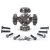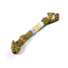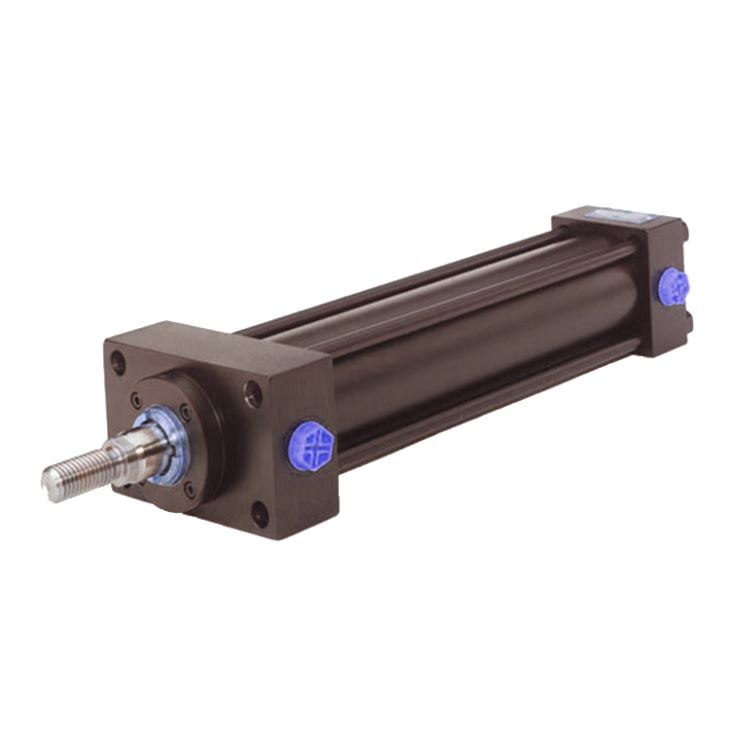

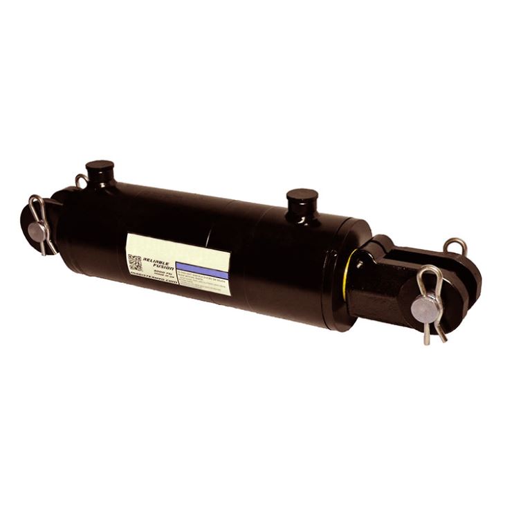
A custom hydraulic cylinder manufacturer supplying welded and tie-rod cylinders for forklifts, aerial work platforms, agricultural machinery, construction equipment and industrial plant. The EG series double-acting single-rod cylinder is the standard building block: a simple, reliable linear actuator with a choice of mounting and connection styles and optional cushioning, produced to the customer's bore, stroke and mounting drawing. Cylinders operate in both industrial duties — presses, cranes, forges and packaging machines — and mobile duties, where hydraulics remains the most power-dense way to produce linear force.
A hydraulic cylinder converts fluid pressure into linear force and motion. Pressure applied to the piston face produces a thrust equal to pressure multiplied by piston area, and that thrust is transmitted directly to the load through the rod — no gears, no levers, no mechanical linkage. That directness is why hydraulics is used wherever a machine has to push, pull, lift or hold something heavy: there are fewer parts between the power source and the work, and fewer parts to wear.
The power density of hydraulics is the other reason it dominates mobile equipment. A hydraulic pump delivers roughly ten times the power density of an electric motor of comparable physical size, which is what allows a compact cylinder to lift a load that would need a much larger electric actuator. The same property explains why hydraulic cylinders appear across such an enormous range of scales, from a small steering ram on a lawn tractor to a cylinder measured in metres on a mining shovel.
Cylinders are used in two broad families of application. Industrial duties run at fixed locations with controlled conditions: hydraulic presses, cranes, forges, injection moulding machines and packaging equipment. Mobile duties run on vehicles where the cylinder is exposed to weather, dust and vibration: agricultural machinery, construction equipment, forklifts, aerial work platforms and marine equipment. The construction of the cylinder — sealing arrangement, rod coating, port style, mounting — has to be matched to which family the duty belongs to, and that is the main reason custom cylinders exist rather than a set of standard catalogue sizes.
This page covers the EG series double-acting single-rod cylinder and the customisation options around it. Related hydraulic products are indexed under the applications section, and the surrounding driveline components — steering systems, universal joints and PTO drive shaft parts — are covered in their own categories.
The EG series is built to the customer's specification rather than selected from a fixed list, so the table below sets out the parameters that define a cylinder and the options available against each. Values marked for confirmation are those that depend entirely on the duty and are quoted per application.
Standard specification envelope. Scroll the table sideways on a mobile device.
| Item | Specification |
|---|---|
| Series | EG series, double-acting single-rod piston cylinder |
| Action | Double acting — hydraulic pressure applied to both extend and retract |
| Cylinder types | Welded construction and tie-rod construction |
| Bore diameter | Produced to drawing — confirm against required thrust and system pressure |
| Rod diameter | Produced to drawing — set by buckling and column strength for the stroke length |
| Stroke | Produced to drawing — confirm from the retracted and extended positions |
| Rated working pressure | Confirm standard and maximum rating for the specific bore and construction |
| Mounting styles | Several connecting modes available; confirm clevis, trunnion, flange or foot mounting |
| Rod end connection | Male thread, or earring (clevis) connection |
| Cushioning | Optional cushioning devices available at either or both ends |
| Rod surface | Hard chrome plating; alternative coatings for corrosive environments on request |
| Seal materials | Selected to the operating temperature and fluid — confirm for the duty |
| Ports | Size and position produced to drawing |
| Assembly and maintenance | Designed for straightforward assembly and disassembly, with replaceable seals |
| Customisation | Bore, stroke, mounting, rod end, port position, cushioning and coating to drawing or sample |
Values to confirm before publication: bore, rod diameter, stroke, rated working pressure, seal materials and port details are quoted per application and cannot be listed as fixed figures for a custom cylinder. What should be added to this table is the available bore range, the available stroke range and the standard pressure rating — for example "bore 40–250 mm, stroke to 2000 mm, rated 250 bar". Without those three ranges, a buyer cannot tell whether the factory is capable of their application at all, which is the first question any hydraulic cylinder enquiry begins with.
The relationship between pressure, bore and thrust is the starting point of every cylinder selection, and it is worth stating plainly because it explains why a small change in bore has a large effect on force.
| Thrust calculation | Thrust equals system pressure multiplied by the effective piston area. Area rises with the square of the bore, so increasing bore diameter from 50 mm to 63 mm increases thrust by about 59 % at the same pressure. That is why bore is normally the first parameter fixed when a duty is specified, and why the pressure rating and the bore must be decided together rather than independently. |
| Extend and retract force | On a double-acting single-rod cylinder the extend and retract forces are not equal, because the rod occupies part of the piston area on the retract side. The retract force is lower by the area of the rod. Where a machine needs similar force in both directions, this difference has to be accounted for at the design stage rather than discovered on commissioning. |
| Why hydraulics rather than pneumatics | Hydraulic fluid is effectively incompressible, so a hydraulic cylinder holds position under load and moves smoothly at low speed. Air is compressible, which makes pneumatic cylinders springy under load and difficult to control precisely. Hydraulics also runs at far higher pressure — typically 10 to 20 times that of a comparable pneumatic system — which is the source of the power density advantage. |
| Why hydraulics rather than electric actuation | For the same physical envelope, a hydraulic system produces substantially more force. A hydraulic pump has roughly ten times the power density of an electric motor of similar size, which is why heavy mobile machinery is hydraulically actuated rather than electrically actuated. The trade-off is that hydraulics needs a power pack, fluid, filtration and leak management, so it suits machines that already have a hydraulic circuit. |
| Structural limits | Thrust is not the only limit on a cylinder. A long stroke with a slender rod will buckle before it reaches its rated thrust, which is why rod diameter is set by column strength rather than by the pressure rating alone. The barrel wall, the rod-to-piston joint and the mounting pin bosses each impose their own limit. Selection is the process of satisfying all of these simultaneously. |
Because the limiting factor shifts with stroke length, a cylinder specified for a short stroke cannot simply be stretched to a longer one by ordering the same bore and rod. Longer strokes usually require a larger rod diameter, and sometimes a larger bore, to keep the cylinder stable and the rod stress within limits. State the stroke when enquiring so buckling can be checked.
The EG series is a double-acting single-rod piston cylinder that reciprocates linearly within a hydraulic system. Its design priorities are structural simplicity, reliable operation, straightforward assembly and disassembly, and ease of maintenance.


| Barrel | The pressure-containing tube. The internal bore is honed to give the piston seal a surface it can run against without scoring, and the wall thickness is set by the rated pressure and the bore diameter. The barrel carries the stress of every pressure cycle, so barrel material and bore finish are the two variables that most affect service life. |
| Piston and rod | The piston separates the extend and retract chambers and transmits thrust to the rod. The rod is hard-chrome plated, because it travels outside the barrel on every stroke and is exposed to dust, moisture and impact. The chrome layer provides wear resistance and corrosion resistance on the one surface that cannot be protected by the housing. |
| Sealing arrangement | A double-acting cylinder needs a piston seal to separate the two chambers and a rod seal to keep fluid in at the gland, plus an external wiper to keep contamination out. Seal material is selected against the operating temperature and the hydraulic fluid, so it should be confirmed for the application rather than assumed. |
| End caps and connections | The end caps close the barrel and carry the ports and the mounting. On a welded cylinder the caps are welded to the barrel; on a tie-rod cylinder they are clamped by four tie rods, which allows the cylinder to be dismantled for resealing without cutting. That difference determines how maintainable the cylinder is in service and is a common reason for choosing one construction type over the other. |
| Cushioning devices | Optional cushioning slows the piston near the end of stroke by trapping fluid and forcing it through a restricted passage. It matters where a cylinder drives a heavy load at speed, because without cushioning the piston strikes the end cap and the shock is transmitted through the whole machine structure. Cushioning can be specified at one end or both. |
| Mounting and rod end | Several connecting modes are available to suit the machine geometry. The rod end can be connected by male thread or by an earring (clevis) connection, and the mounting style at the cylinder body is selected to match how the load is applied. |
The rod end is the interface between the cylinder and the driven part. Two connection styles are offered, and the choice is normally determined by whether the load is a straight push or involves angular movement through the stroke.


Male thread suits a push-only or lightly guided load, or where the rod end takes a threaded fitting such as a rod eye, a spherical bearing or a locknut arrangement. Earring (clevis) connection suits loads that swing through an arc during the stroke, because the pin allows the cylinder to follow the load rather than being loaded in bending. Where the machine geometry causes the load direction to change through the stroke, an earring or a spherical bearing at the rod end is normally required — a rigid threaded connection in that situation bends the rod.
Selection follows a fixed sequence, because each decision constrains the next. Working through these five steps in order avoids the two most common errors: choosing a bore that produces too little force, and choosing a cylinder that buckles because the rod is too slender for the stroke.
What to send with an enquiry: required thrust or the load to be moved, available system pressure, required stroke, mounting style, port size and position, rod end connection, operating environment and the quantity required. If the cylinder is replacing an existing one, a drawing or a photograph with principal dimensions measured from the original is usually faster and more reliable than a specification list.
Both constructions are produced for this series, and the choice between them is a maintenance decision as much as an engineering one.
| Welded cylinder | The end caps are welded to the barrel to form a single pressure-containing body. Welded construction is generally more compact for a given bore and pressure, and is the usual choice for mobile equipment where the cylinder is exposed and must be as robust and as small as possible. The disadvantage is serviceability: because the caps are welded, the cylinder cannot be opened for resealing in the field without cutting, so a seal failure normally means the cylinder is removed and rebuilt in a workshop. |
| Tie-rod cylinder | The end caps are clamped to the barrel by four tie rods running the length of the cylinder. This allows the cylinder to be dismantled on the machine by removing the tie rods, which makes seal replacement and inspection far quicker and is the reason tie-rod construction is common in industrial plant where downtime is expensive. The trade-off is a slightly larger envelope for the same bore, and the tie rods must be re-torqued correctly on reassembly — uneven torque distorts the barrel and causes the piston seal to leak. |
| How to choose | Choose welded construction where envelope size and resistance to external damage dominate: mobile machinery, construction equipment and agricultural implements. Choose tie-rod construction where the cylinder will need resealing during its working life and the machine can accept a slightly larger cylinder: industrial plant, presses and fixed equipment. Where the duty is severe enough that both matter, tie-rod with a protective shroud is often the compromise. |
| Pressure capacity | Both constructions are pressure-rated for their bore and wall thickness rather than by construction type alone, so the rating is confirmed per cylinder rather than assumed from the type. State the system pressure and the relief valve setting when enquiring, because a cylinder rated for a lower pressure must not be protected by a relief valve set higher than its rating. |
The EG series and the custom cylinders built around it serve both fixed industrial plant and mobile machinery. The two groups differ mainly in how exposed the cylinder is and how it is maintained.
| Forklift trucks | Mast lift, tilt and side-shift cylinders, where compact dimensions and a reliable rod seal matter because the cylinder operates continuously through a shift. |
| Aerial work platforms | Boom lift, levelling and outrigger cylinders, where cushioning is usually required and the cylinder is subject to an inspection regime because it carries people. |
| Agricultural machinery | Loader lift and bucket cylinders on tractors, plus implement cylinders on balers, mowers and ploughs, working in dust and weather with limited maintenance access. |
| Construction equipment | Excavator boom, arm and bucket cylinders and loader cylinders, where shock loading is severe and both rod strength and mounting rigidity are critical. |
| Industrial presses and forges | High-force cylinders where the pressure rating and the structural integrity of the barrel and end caps dominate the specification. |
| Packaging machinery | Fast-cycling cylinders where cushioning and seal life under continuous operation matter more than raw force. |
| Marine and offshore equipment | Cylinders where the rod coating and seal material must resist salt exposure, and where a stainless or specialised rod finish may be needed. |
| Municipal vehicles | Tailgate, tipper and sweeper cylinders, where the duty cycle is intermittent but the cylinder is exposed to road salt and weather. |
The related driveline and machine components supplied alongside these cylinders include agricultural gearboxes and universal couplings, so a complete implement assembly can be sourced from the same supplier rather than assembled from several.
Most hydraulic cylinder failures that are not caused by contamination are caused by installation. The checks below cover the points that account for the majority of premature failures.
Installation and maintenance guidance. Scroll the table sideways on a mobile device.
| Item | What to check | Why it matters |
|---|---|---|
| Mounting alignment | Confirm the mounting pin axes are parallel and that the cylinder can align itself with the load through the full stroke. Check for binding by stroking the cylinder slowly by hand before applying pressure. | A cylinder that is forced to operate out of alignment loads the rod in bending. The gland bearing takes that load and the rod seal fails early — the most common cause of a repeat failure on an otherwise sound cylinder. |
| Cleanliness before connection | Wash the cylinder and surrounding area before breaking any hydraulic connection, and cap or plug both the ports and the hose ends immediately after disconnection. | Contamination introduced at this step circulates through the system and scores the bore and seals. It is the single most preventable cause of a new cylinder failing within weeks. |
| Hydraulic fluid | Confirm the fluid type and viscosity grade against the seal material, and check the fluid condition and filter before commissioning. | The wrong fluid attacks the seals; contaminated fluid abrades them. Both shorten seal life dramatically and neither is visible until leakage begins. |
| Bleeding and first cycles | Cycle the cylinder slowly through its full stroke several times at low pressure to expel air, then check for weeping at the ports and gland. | Trapped air causes spongy movement and local overheating that damages seals. Catching a weeping port at commissioning is far cheaper than catching it after the machine is in production. |
| Relief valve setting | Confirm the system relief valve is set at or below the cylinder's rated pressure. | A relief valve set above the cylinder rating means the cylinder becomes the weakest point in the circuit and will eventually fail at the barrel or the end cap rather than at a seal. |
| Rod protection | Where the cylinder works in falling debris or impact, fit a rod guard or bellows. Wipe the exposed rod before it retracts. | Chrome is hard but not indestructible. A single dent or scratch on the rod destroys the rod seal on every subsequent stroke, so the seal cannot be fixed without replacing or re-chroming the rod. |
| Seal replacement | Replace seals when weeping first appears rather than when leakage becomes heavy, and inspect the rod and bore for damage at the same time. | A weeping cylinder left running will damage the rod surface, turning a seal kit replacement into a cylinder rebuild. Inspecting the rod at reseal time is what prevents the same failure recurring. |
| Storage | Store cylinders with the rod retracted and the ports plugged, in a dry location. | An exposed rod in storage corrodes, and a corroded rod ruins the seal on first operation. Most stored-cylinder failures happen before the cylinder is ever fitted. |
Send the required thrust or load, system pressure, stroke, mounting style, port size and position, rod end connection, operating environment and quantity — or simply the drawing or the dimensions of the cylinder being replaced. We will confirm the design and reply with price and lead time.
Request a Quotation* Bore, rod diameter, stroke, rated pressure, seal material and port details are produced to order and are confirmed in the quotation against your specification. Available bore and stroke ranges and the standard pressure rating should be added to the specification table above from the factory data. Certifications and pressure ratings quoted in the source structured data should be verified before being reused.
Address
Luotuo Industrial Area, Zhenhai District, Ningbo City, China